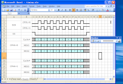
Suppose I'm going to draw the following diagram,

- Create a new sheet and reduce the width of all columns to 20 pixels or less. The width of a column will be used as the minimum clock width in the whole diagram.
- In the Border Toolbar, click "Draw Borders" to open the "Draw Border Toolbar". Choose the line type if you like.


- Use the "pencil" to draw your diagram, use the "rubber" to erase.

- For signals of data bus type, use "Fill Color" or "Fill Pattern".
- Cut/Copy and Paste also works, so you just need to copy the same pattern a few times to create the whole diagram.
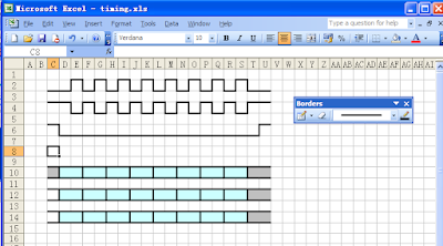
- Add text in cells as comments, and change cell size if needed. Now I'm finished:
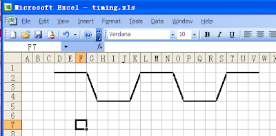
- If you need to show the exact slope of rising/falling edge of a signal, you can merge some vertical cells and use a diagonal line.


Advantages
- No additional software is needed to create or view the diagram. I believe everyone has Excel, or something equivalent such as Open Office Calc or Google Spreadsheets(which don't support drawing borders at the moment).
- Easier and quicker comparing with general purpose drawers such as MS Paint.
- Text-based(or rather vector-based) document type has smaller file size than pictures, especially when the diagram is very big.
Problems
- Won't show up if directly pasted to Word or some online html editors(the blogger editor, for example). They seems to have different understandings about styles of form cell borders with Excel. My current workaround is to printscreen to a picture or print to a PDF(with PDFCreator).
Alternative solutions
- General Drawers, such as MS Paint, GIMP, Inkscape.
- General Diagram Editors, such as Dia, Microsoft Visio, Smart Draw
- SynaptiCAD Timing Diagram Editor, professional commercial software, trail version is available.


